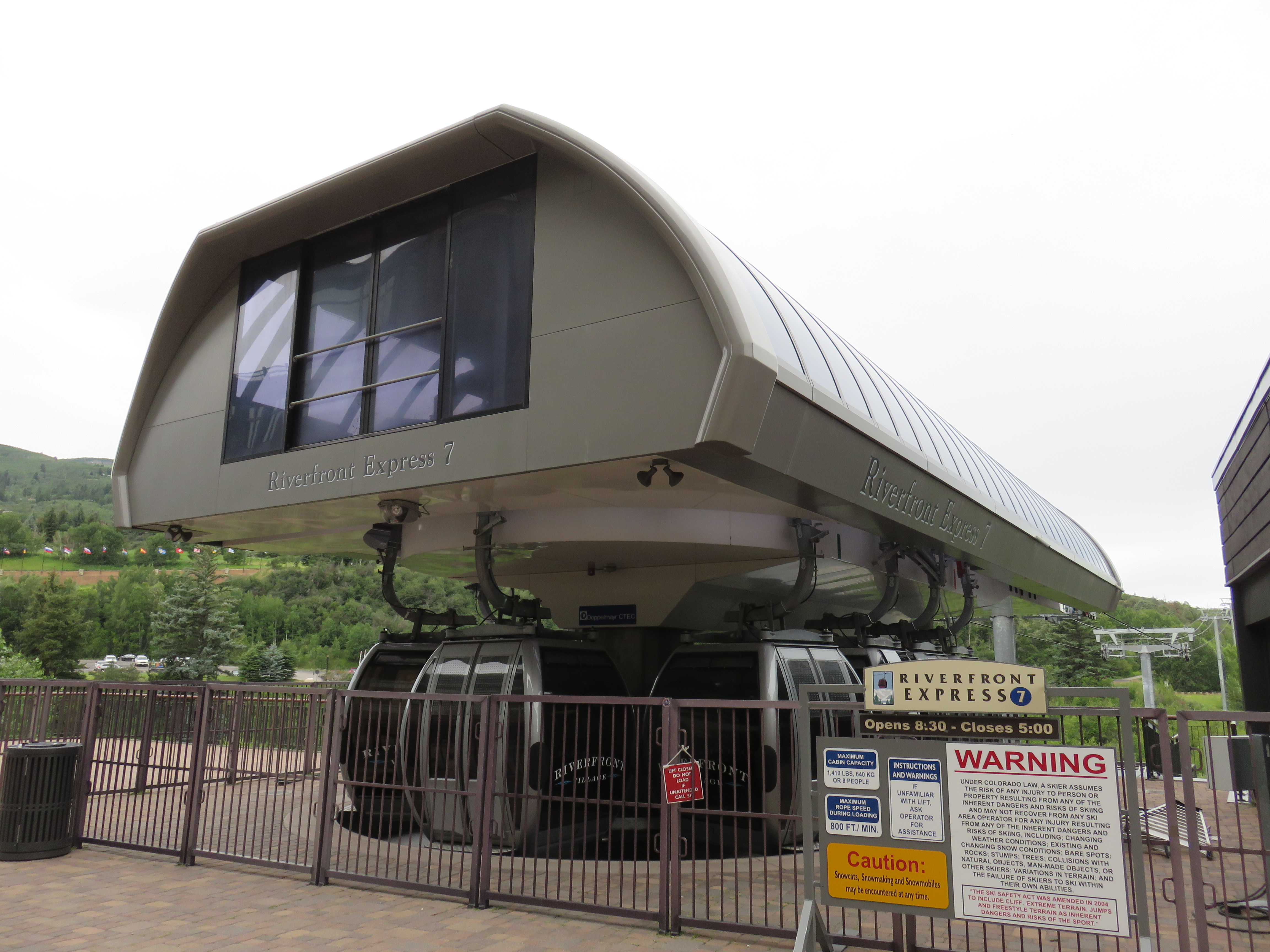
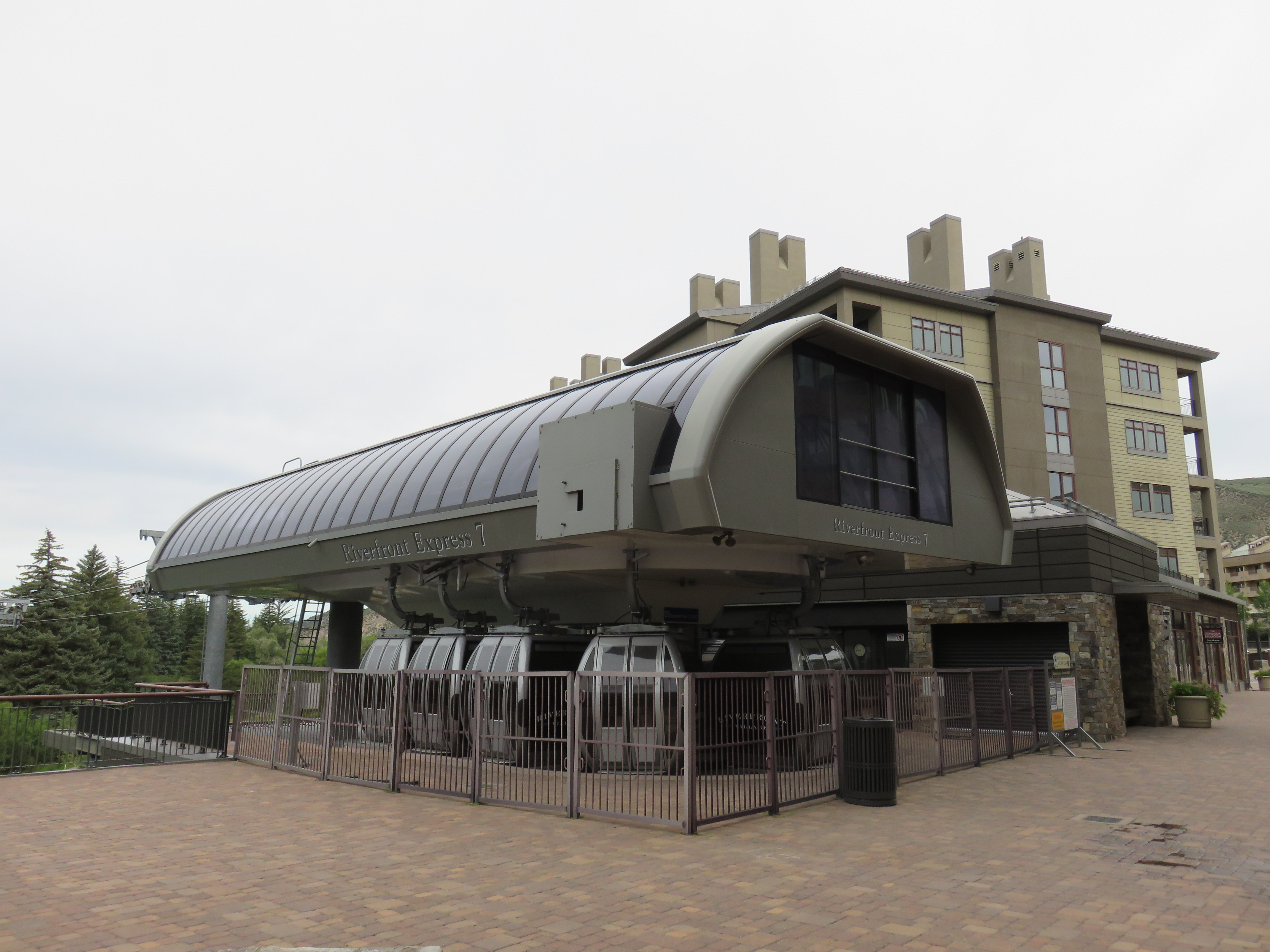
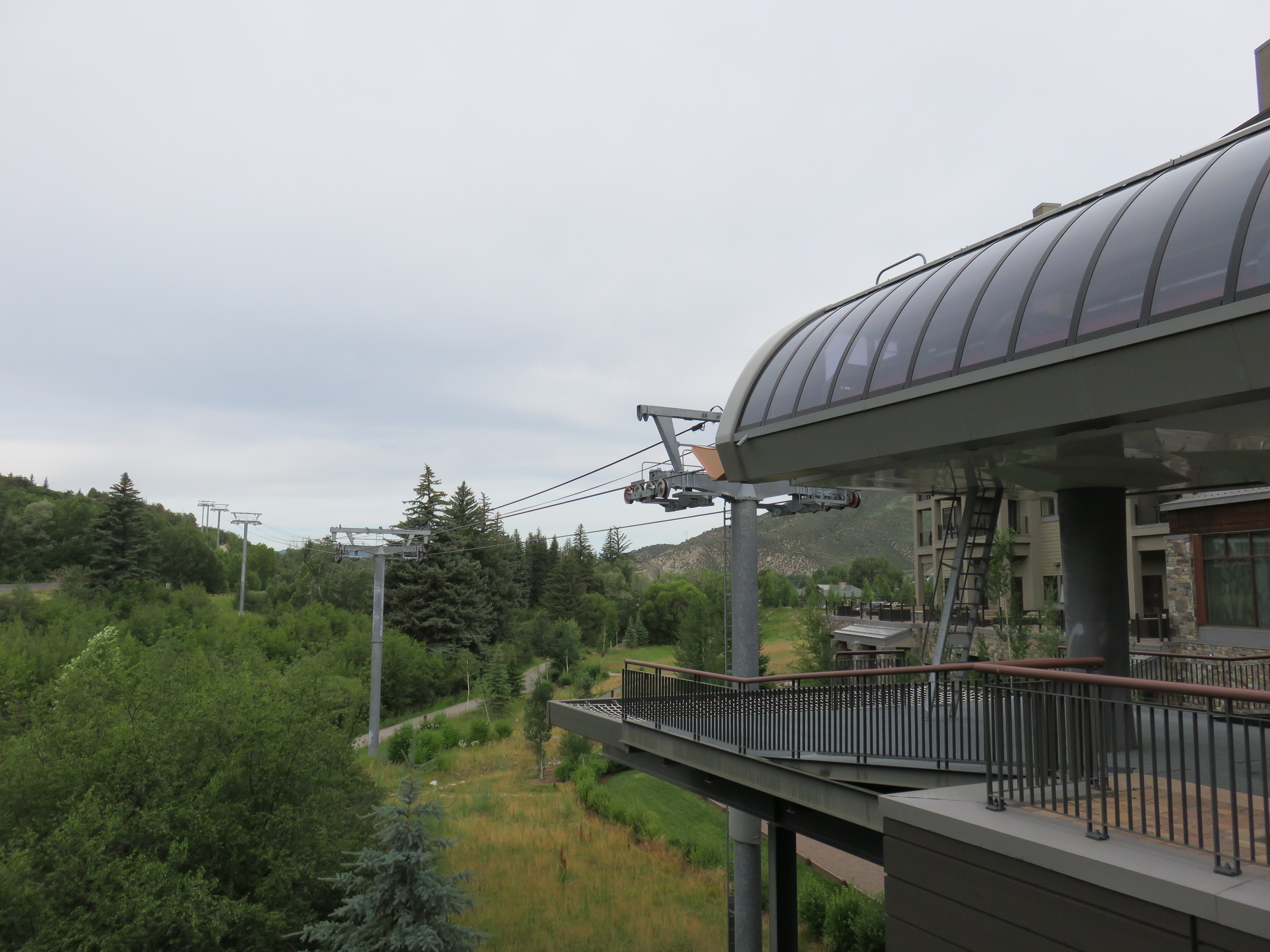
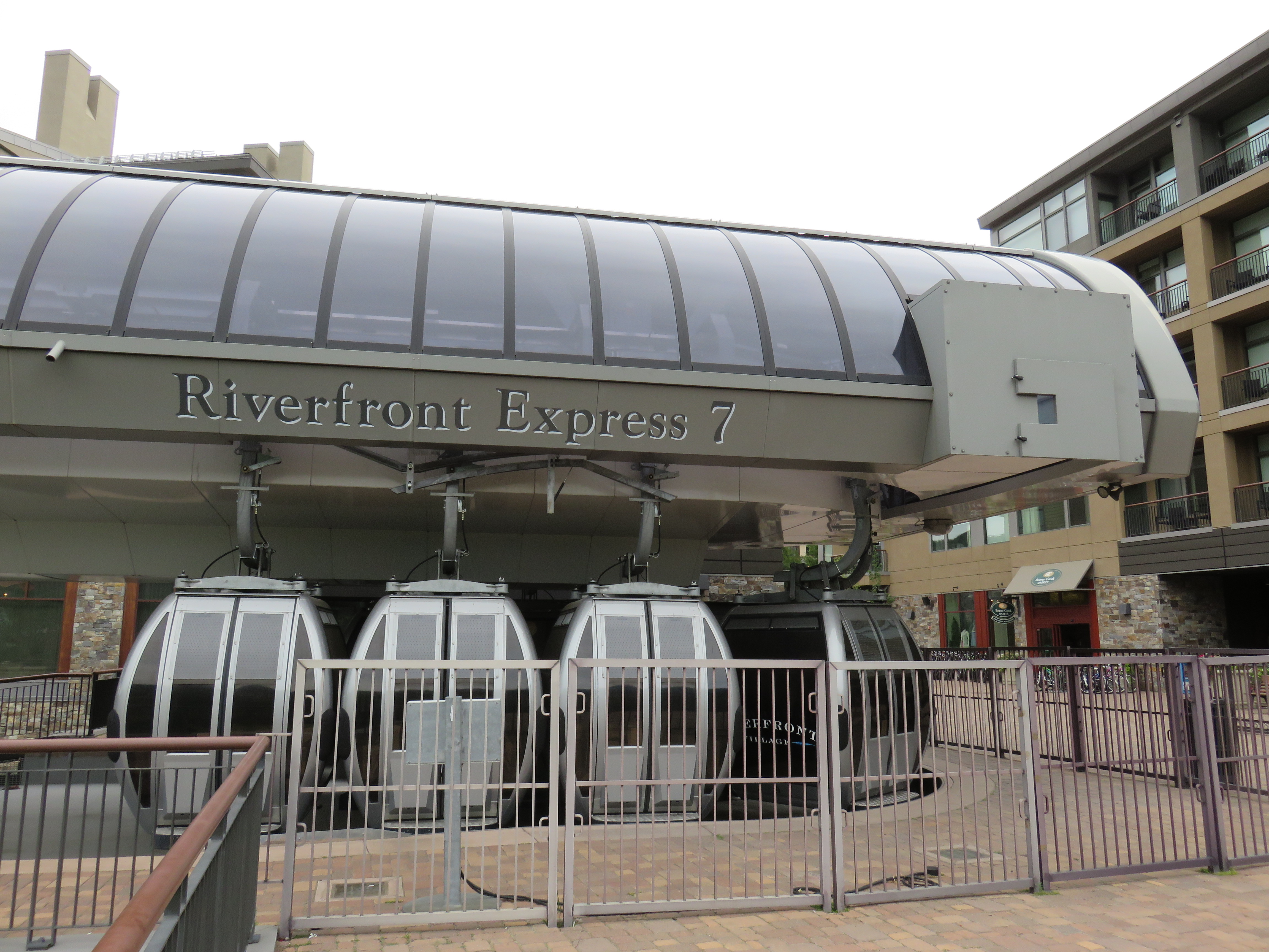
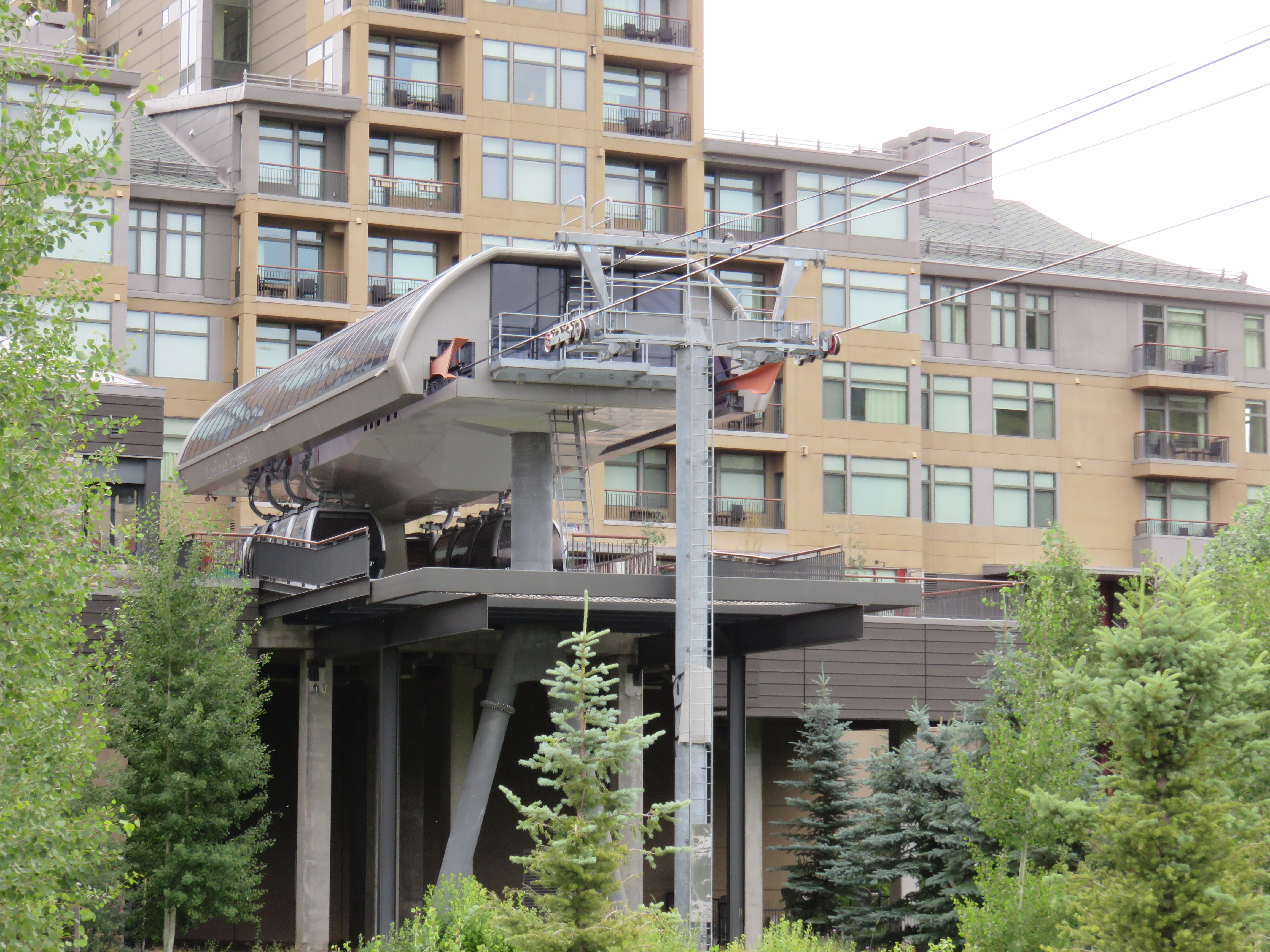
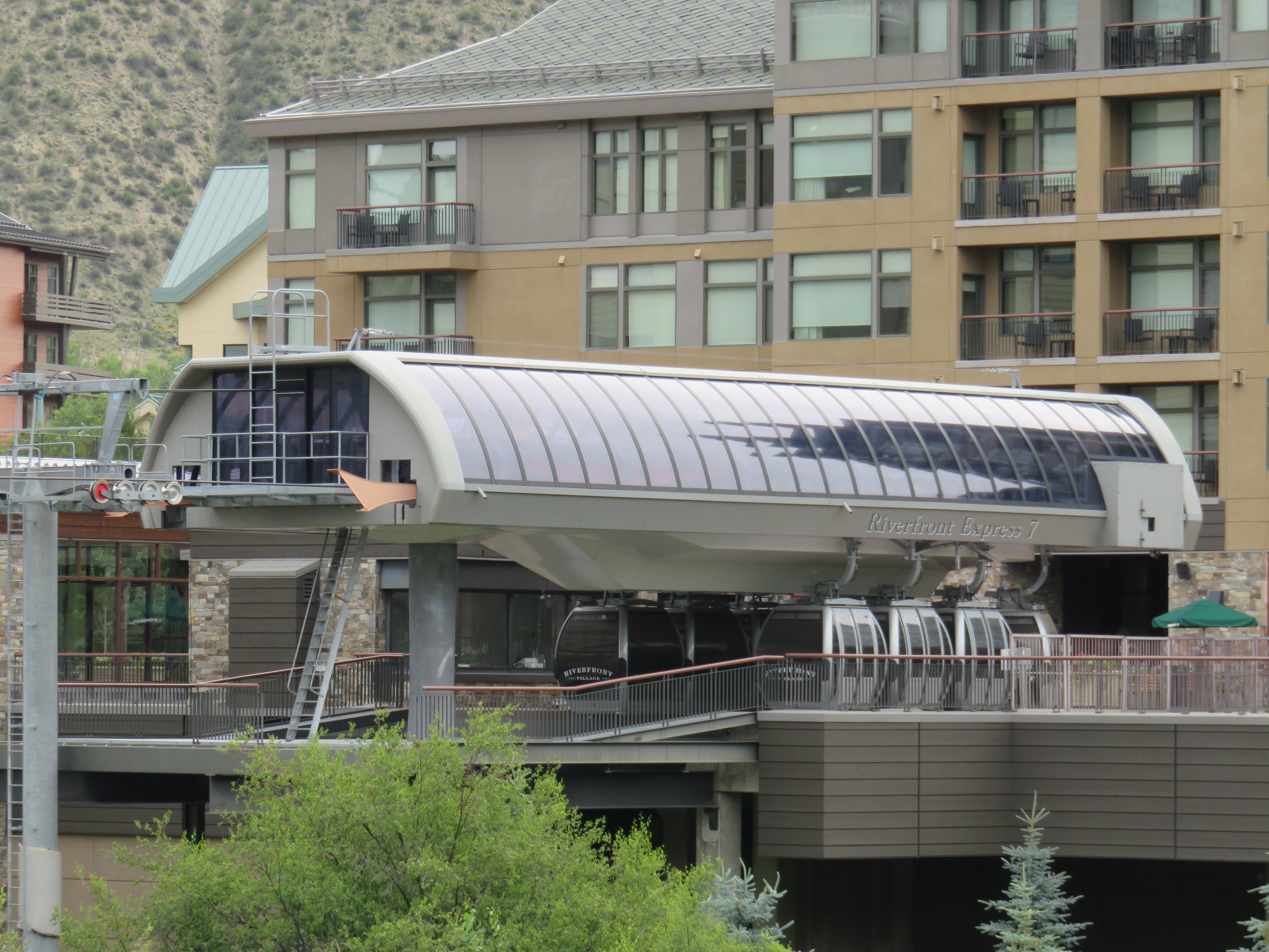
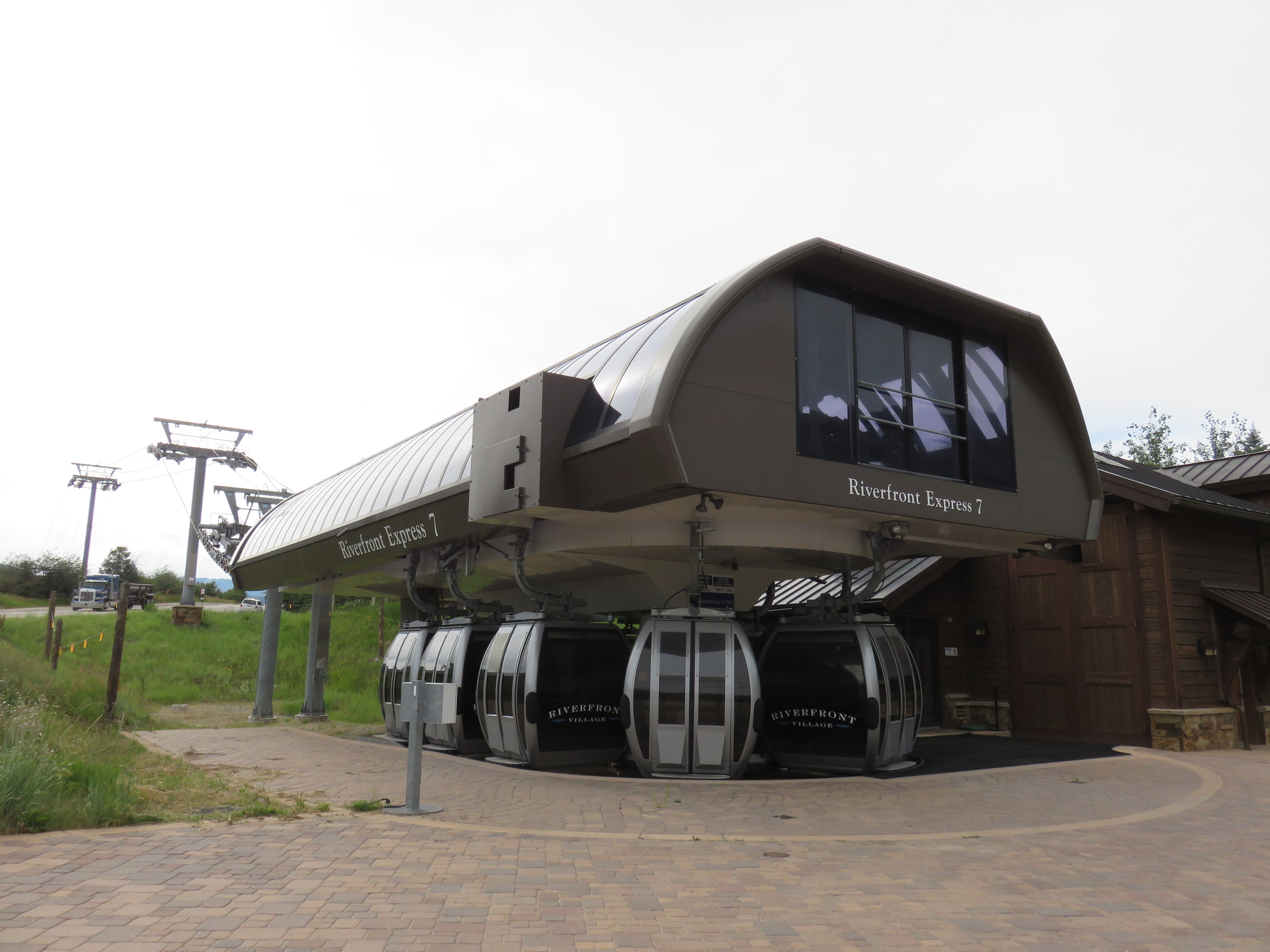
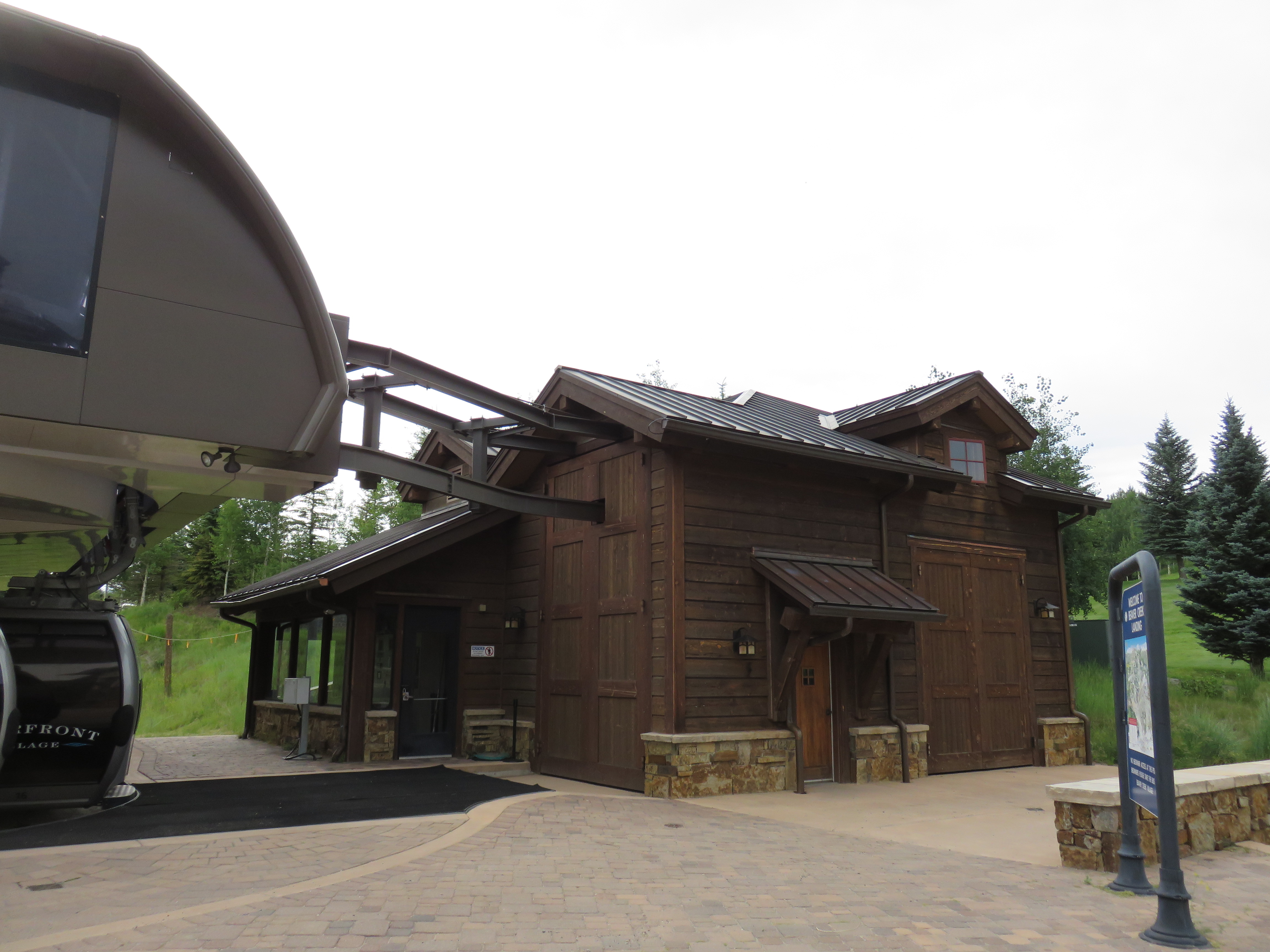
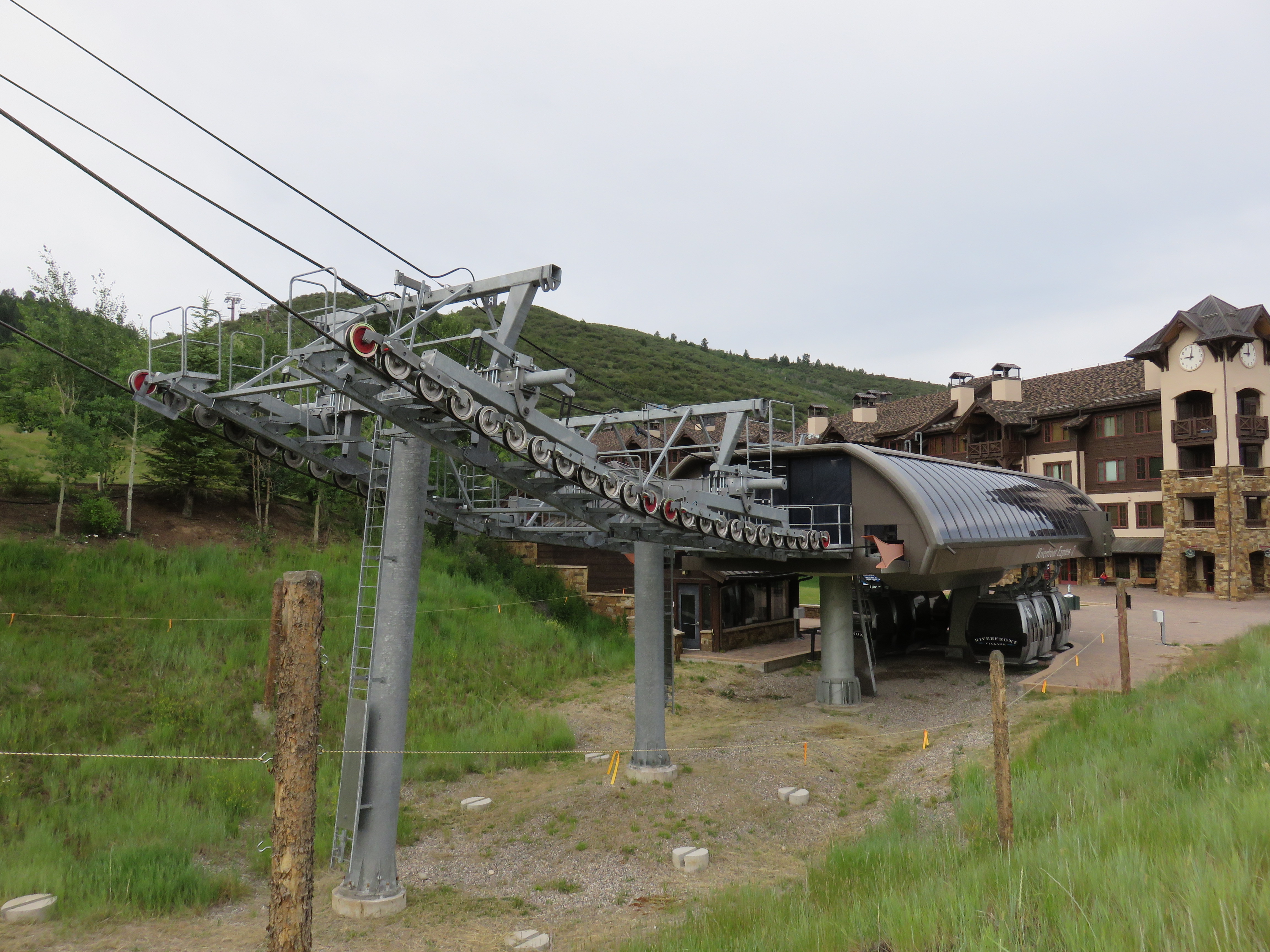
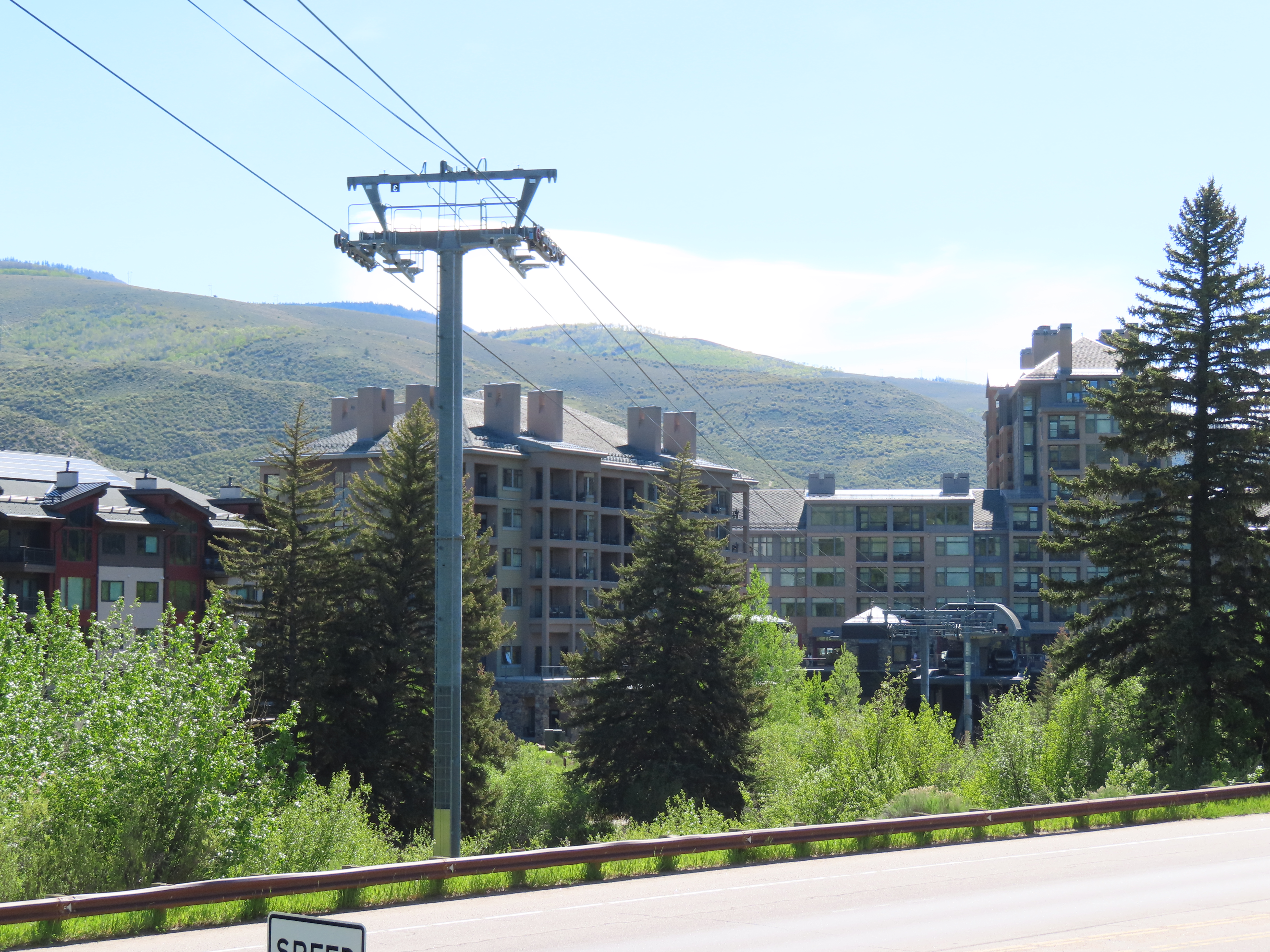
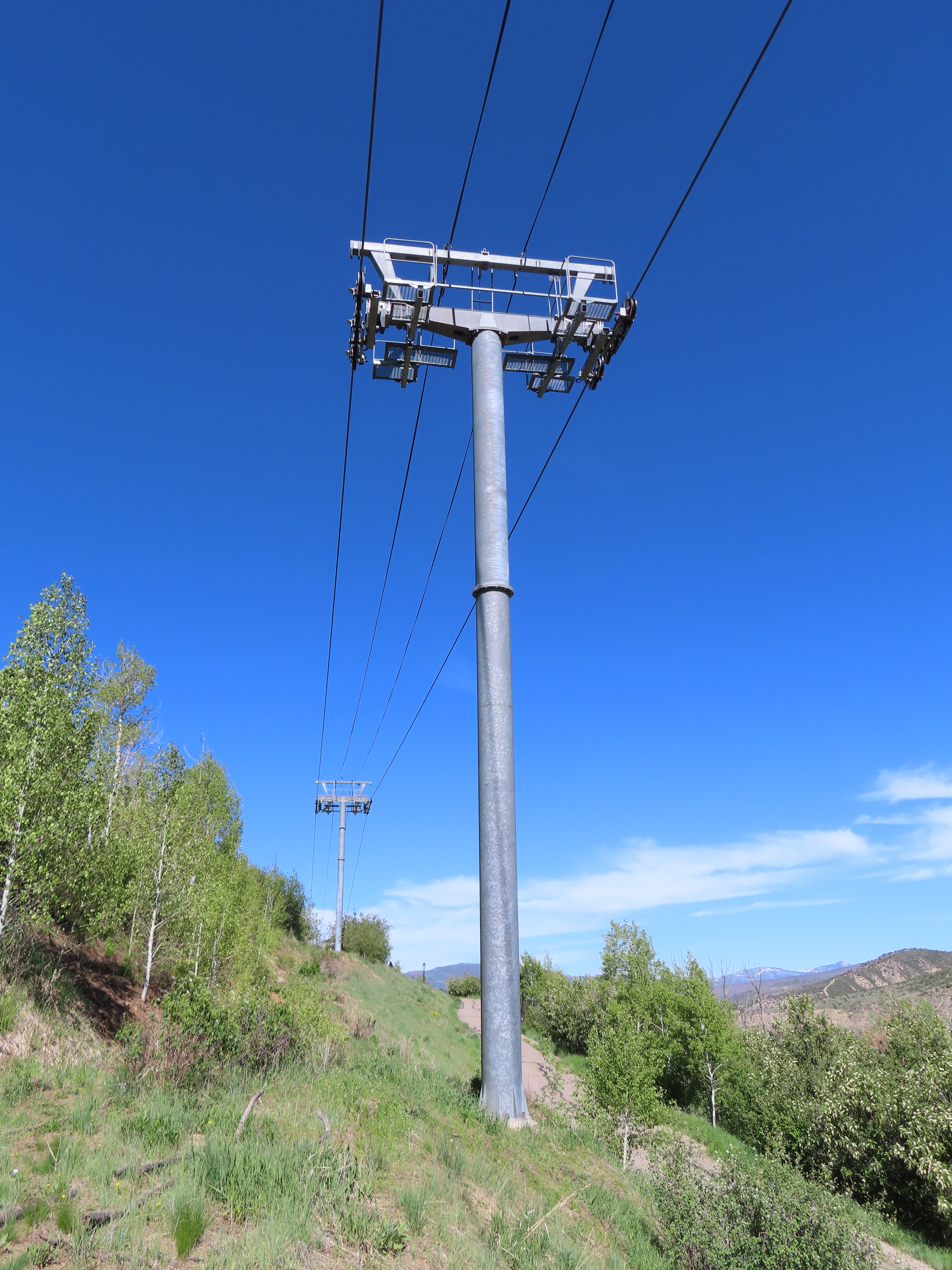
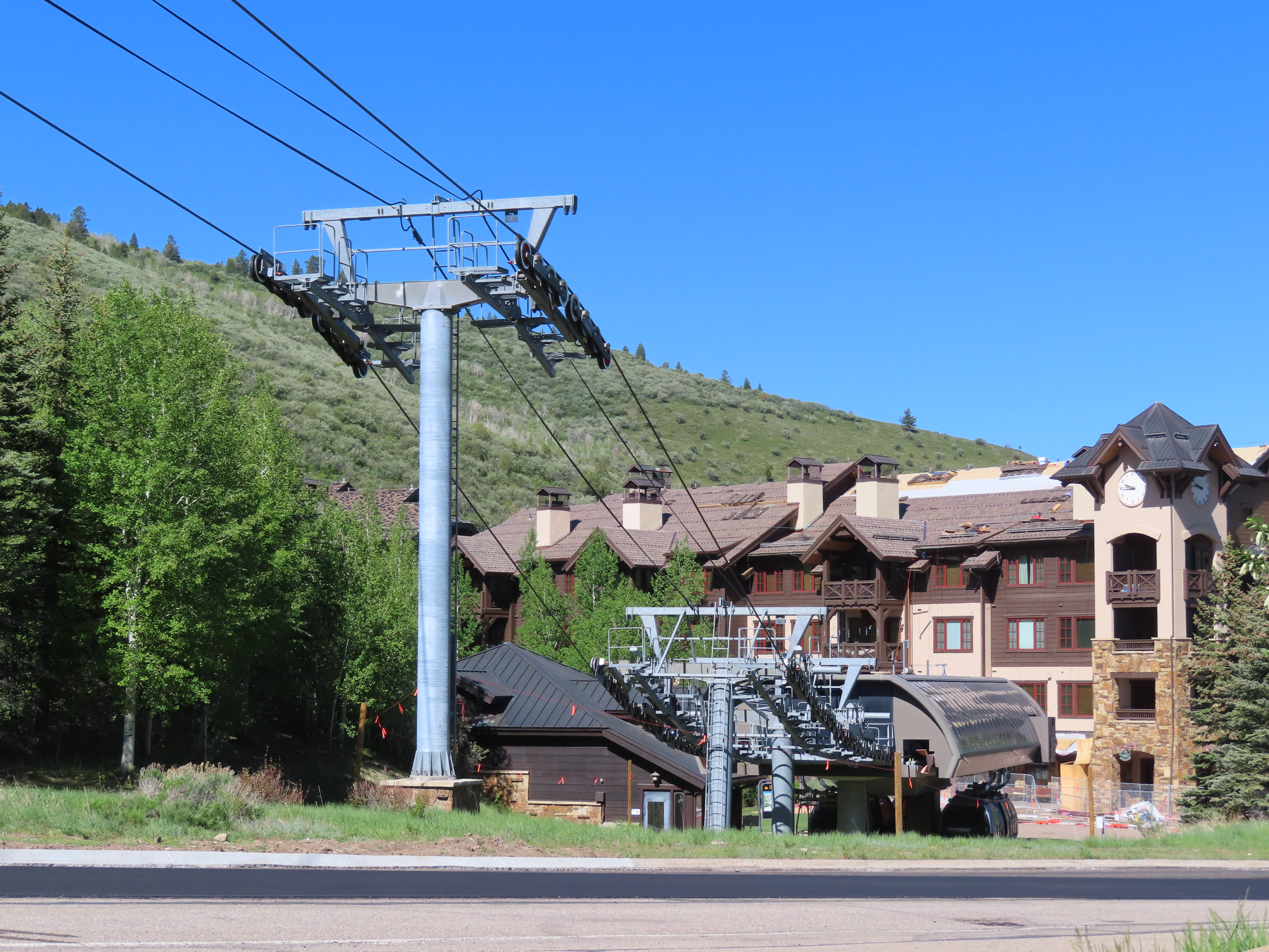
Westin Riverfront terminal.Another view of the Westin station.View towards Beaver Creek Mountain.Loading area with cabins parked for the summer.This lift was built well before the buildings around it.Doppelmayr Uni-G gondola terminal.Beaver Creek Mountain station with cabin maintenance bay.Cabin maintenance facility with integrated operator house.Towers 8 and 9.View crossing over US6.Middle part of the lift line.Looking down the line.The top three towers.Doppelmayr Worldbook entry.
2 thoughts on “Riverfront Express – Beaver Creek, CO”
Billy B.February 17, 2020 / 6:22 pm
From what I understand, terminal carrier parking (as shown here) uses hydraulics to lift tire banks and allow carriers to be freely positioned on the running rail within the terminal. However, I’ve never worked hands-on with a system like this and am curious about some of the mechanical specifics.
How are the tire banks integrated with the PTO belt for the rest of the terminal? Can they be easily disconnected before they are raised, or are the banks powered by a separate motor similar to a spacer setup? How are the carriers spaced out when the lift is started back up again? Is it just manual spacing followed by a couple of spacing laps, or does the machine have a way to space out the carriers when they are being relaunched from being parked?
I know that is a lot of questions. I would appreciate answers to these and anything else I didn’t think of relating to terminal carrier parking. Just trying to understand a process that has stumped me for a little while.
The tire banks that raise are linked via v-belts to the rest of the terminal just as you would find in any other detachable. There are 3 separate sections that each raise independently from one another via small hydraulic cylinders. Coil springs then hold each section in place during normal operation. Because the banks only raise 1.5 inches or so, the v-belts can accept this movement and do not need to be uncoupled.
Launching cabins is accomplished by a feeder clutch/brake unit on the outgoing side of each terminal. The lift is put into feed mode with the banks up and a cabin is moved into the clutch. After a certain number of impulses, the cabin is automatically launched onto the rope. This occurs simultaneously at the drive and return station and is repeated until 3 cabins remain in each station. Those cabins are then spaced out appropriately and the banks are then lowered. A different clutch/brake unit then continually spaces the rest of the line during normal operation although this is not normally needed.


From what I understand, terminal carrier parking (as shown here) uses hydraulics to lift tire banks and allow carriers to be freely positioned on the running rail within the terminal. However, I’ve never worked hands-on with a system like this and am curious about some of the mechanical specifics.
How are the tire banks integrated with the PTO belt for the rest of the terminal? Can they be easily disconnected before they are raised, or are the banks powered by a separate motor similar to a spacer setup? How are the carriers spaced out when the lift is started back up again? Is it just manual spacing followed by a couple of spacing laps, or does the machine have a way to space out the carriers when they are being relaunched from being parked?
I know that is a lot of questions. I would appreciate answers to these and anything else I didn’t think of relating to terminal carrier parking. Just trying to understand a process that has stumped me for a little while.
LikeLiked by 1 person
The tire banks that raise are linked via v-belts to the rest of the terminal just as you would find in any other detachable. There are 3 separate sections that each raise independently from one another via small hydraulic cylinders. Coil springs then hold each section in place during normal operation. Because the banks only raise 1.5 inches or so, the v-belts can accept this movement and do not need to be uncoupled.
Launching cabins is accomplished by a feeder clutch/brake unit on the outgoing side of each terminal. The lift is put into feed mode with the banks up and a cabin is moved into the clutch. After a certain number of impulses, the cabin is automatically launched onto the rope. This occurs simultaneously at the drive and return station and is repeated until 3 cabins remain in each station. Those cabins are then spaced out appropriately and the banks are then lowered. A different clutch/brake unit then continually spaces the rest of the line during normal operation although this is not normally needed.
LikeLiked by 2 people